Gigabyte Z170X SOC Force Overclocking Motherboard Review
Author: Dennis GarciaBoard Layout and Features
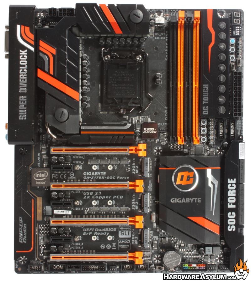
The motherboard features a matte black PCB with orange expansion slots and color accents on the various heatsinks. I have said this many times on the Hardware Asylum Podcast and on Social Media that the Gigabyte Z170X SOC Force has “Curb Appeal”. While that term is normally reserved for cars you cannot ignore that this is an attractive motherboard, even if you aren’t a fan of black and orange.
Like on previous OC series motherboards the Z170X SOC Force is designed for mutli-GPU applications and features a slot layout to support up to four GPUs at one time.
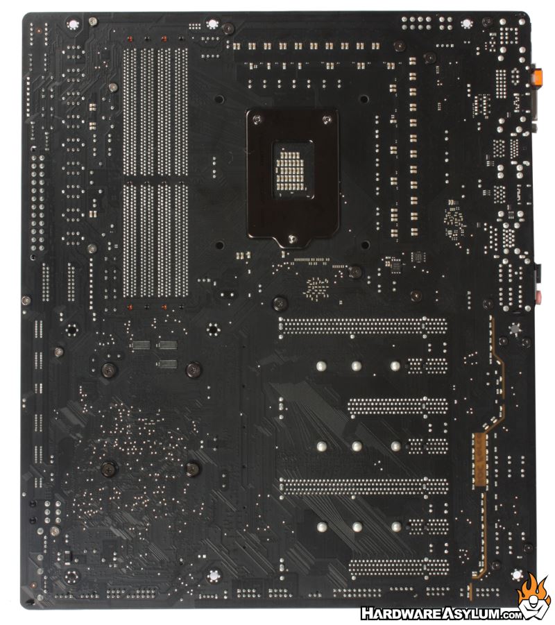
Looking at the back of the motherboard we can get an indication as to how the PCI Express slots are wired and determine which slots are primary and secondary in terms of bandwidth. This motherboard features a handful of surface mounted resistors and ICs which is likely a result of the more complex board design.
Below the CPU socket and above the first PCI Express slot you will see a tiny patch of solder connections. This is the location of the PLX switch chip that multiplies the available PCI Express lanes and allows the board to run proper 4-Way SLI.
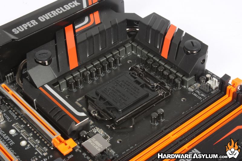
On the Z170X-SOC Force you will find a total of twenty two (22) power phases for the CPU, Ring and internal graphics. This might be one of the largest PWMs we have seen in a really long time and is a common feature on high-end Gigabyte motherboards.
The SOC uses the new 4th generation IR digital power controllers and 3rd generation PowIRstage ICs Isense technology for better current accuracy. This helps evenly distribute the thermal loading between the PowerIRstage ICs, preventing the overheating of each individual PowerIRstage. End result: longer lifespan and better reliability.
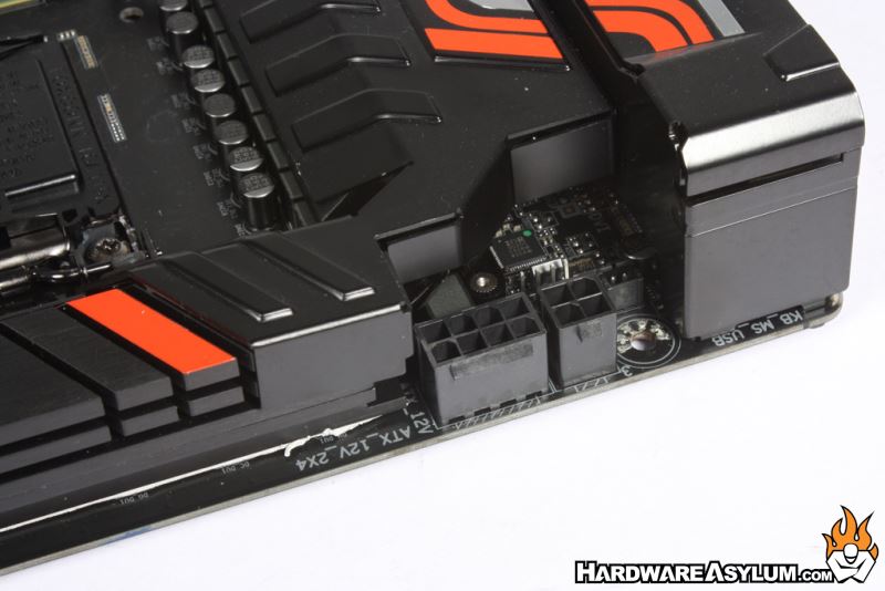
Behind the PWM cooler you'll find the CPU Power connection made up of a single 8-pin and secondary 4-pin connector. Given the location the cables they should be easy to hide in any modern chassis and easy to remove given the space between the power plug and I/O panel.