Quantum Force P67 Rattler Motherboard Review
Author: Dennis Garcia
Published: Tuesday, May 03, 2011
Board Layout and Features
Quantum Force motherboards have typically followed the Bloodrage color scheme with black PCBs and bright red accent parts. The Rattler is no exception yet appears to be far less colorful than previous editions. You'll find red accent parts on the video slots, memory banks and I/O Connectors.
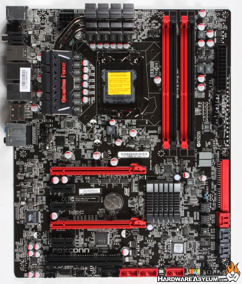

The back of the motherboard is extremely clean and devoid of any surface components. The solder points indicate that both video card slots are hardwired to 16x lanes each giving us the indication that full bandwidth is available in both positions.
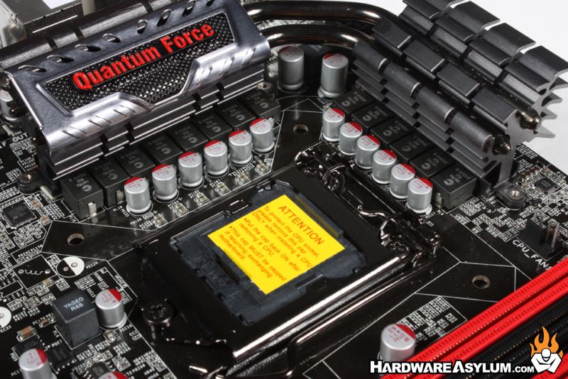
Power is extremely important when overclocking to ensure the best stability. On the Rattler you will find a total of 16 power phases with 12 being dedicated to the CPU, two for the VTT and two for memory. The Direct-Fet PMW is cooled by a dual heatpipe system with plenty of surface area.
Power is extremely important when overclocking to ensure the best stability. On the Rattler you will find a total of 16 power phases with 12 being dedicated to the CPU, two for the VTT and two for memory. The Direct-Fet PMW is cooled by a dual heatpipe system with plenty of surface area.
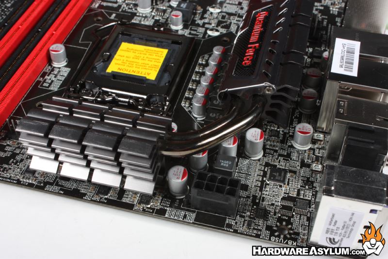
Behind the PWM cooler you'll find the 8 pin CPU power connector with plenty of room around the release tab. This may sound like a minor thing but all too often there isn't enough room to install or remove this power plug.
Dual channel memory comes standard on the Sandy Bridge and the Rattler supports DDR3 modules up to 2133Mhz with a maximum of 16GB usable. 24pin ATX power is located in the traditional location near the upper edge of the motherboard.
Dual channel memory comes standard on the Sandy Bridge and the Rattler supports DDR3 modules up to 2133Mhz with a maximum of 16GB usable. 24pin ATX power is located in the traditional location near the upper edge of the motherboard.

Hardware Overclocking
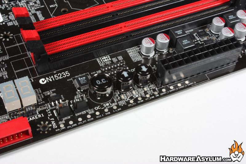
Near the memory slots you'll find a very unique feature that Foxconn as simply named an OC Button. To use this feature simply press the O.C. button at which activates the two adjustment switches. Pressing the up arrow will increase the BCLK while the down arrow will decrease the BCLK. You can see these adjustments in real time on the debug LED and since they are hardware based can be used at any time.
Sadly the usefulness of the O.C. buttons is extremely limited on the P67 since they adjust the BCLK in 1Mhz increments instead of the expected 0.1Mhz that are commonly used. Below the O.C. button array you'll find a whole mess of voltage test points that are great to use when trying to determine exact voltage settings for maximum stability.
Sadly the usefulness of the O.C. buttons is extremely limited on the P67 since they adjust the BCLK in 1Mhz increments instead of the expected 0.1Mhz that are commonly used. Below the O.C. button array you'll find a whole mess of voltage test points that are great to use when trying to determine exact voltage settings for maximum stability.