MSI Z87 MPower Motherboard Review
Author: Dennis Garcia
Published: Thursday, July 11, 2013
Board Layout and Features
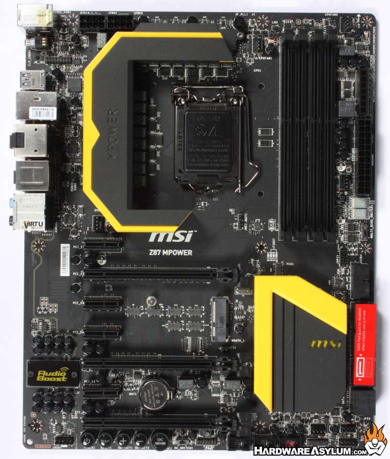
The MSI MPower uses a matte black PCB accented by yellow on the two heatsinks. The matte finish tends to show condensation better than the glossy cousin and the yellow color is part of the OC branding.
Expansion slots are completely black and use the paddle style PCI Express card locks.
Expansion slots are completely black and use the paddle style PCI Express card locks.
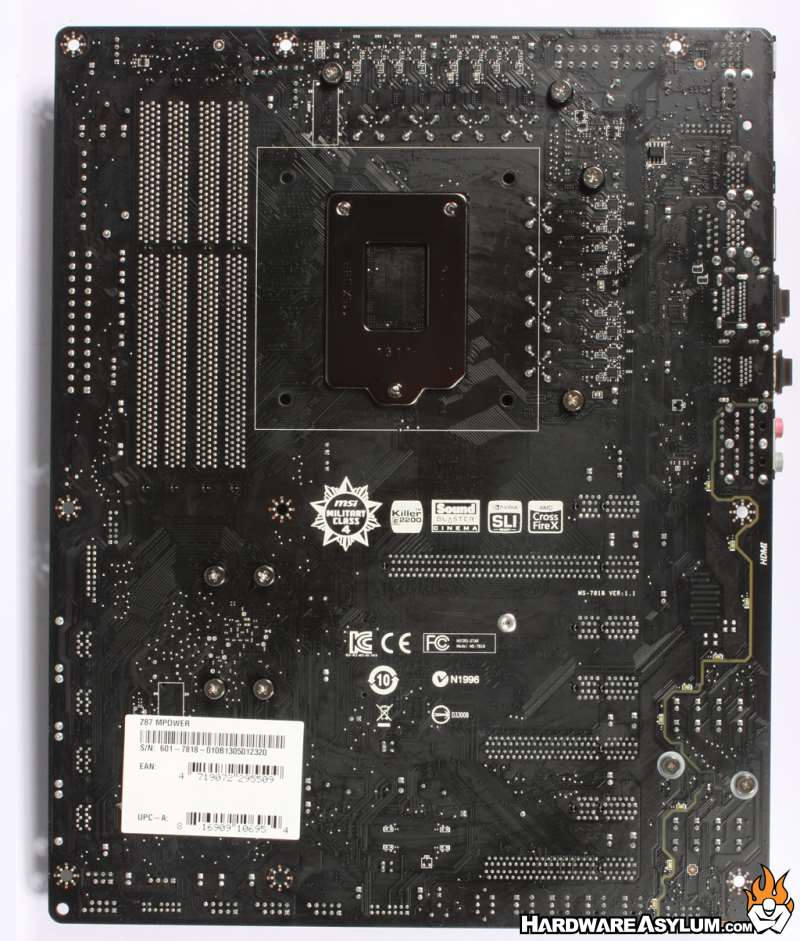
Flipping a motherboard over can tell you a lot about its construction. Here we can see that the back of the motherboard is virtually devoid of any surface components and features only minimal circuitry.
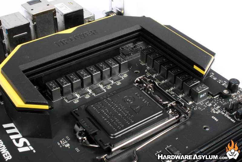
Moving to the CPU we can see the dark chrome CPU socket hardware positioned next to the array of PWM components. The power design uses the latest military class 4 grade components for longer life, better power efficiency and stability. You will find a total of 16 DigitALL power phases on the Z87 MPower covered by an extremely large heatsink that wraps around three sides of the processor. The yellow graphic almost looks like a stylized "M".
Moving to the CPU we can see the dark chrome CPU socket hardware positioned next to the array of PWM components. The power design uses the latest military class 4 grade components for longer life, better power efficiency and stability. You will find a total of 16 DigitALL power phases on the Z87 MPower covered by an extremely large heatsink that wraps around three sides of the processor. The yellow graphic almost looks like a stylized "M".
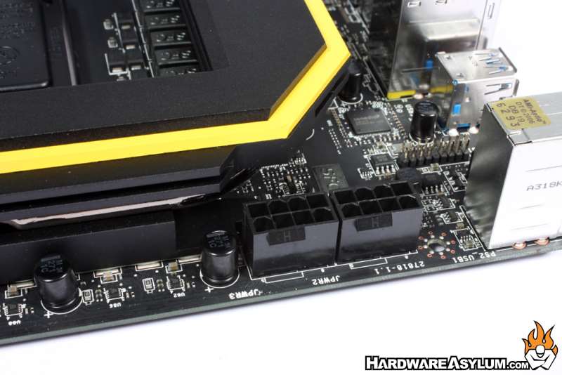
Behind the PWM cooler you will find two 8-pin 12v CPU power connectors that will feed power directly into the processor. Most overclocking motherboards are somewhat light when it comes to supplying power to the CPU and while a single 8-pin is recommended by Intel having a secondary plug is added insurance under extreme overclocking conditions.
Dual channel memory comes standard on the Haswell processor and the Z87 MPower supports standard speed DDR3 modules up to 1600Mhz with overclocking support up to 3000Mhz. A maximum of 32GB is addressable however a 64-bit OS is required to access it all. 24pin ATX power is located in the traditional location near the upper edge of the motherboard and out of the primary airflow.
Dual channel memory comes standard on the Haswell processor and the Z87 MPower supports standard speed DDR3 modules up to 1600Mhz with overclocking support up to 3000Mhz. A maximum of 32GB is addressable however a 64-bit OS is required to access it all. 24pin ATX power is located in the traditional location near the upper edge of the motherboard and out of the primary airflow.
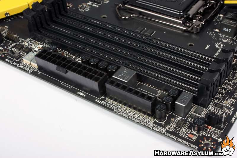
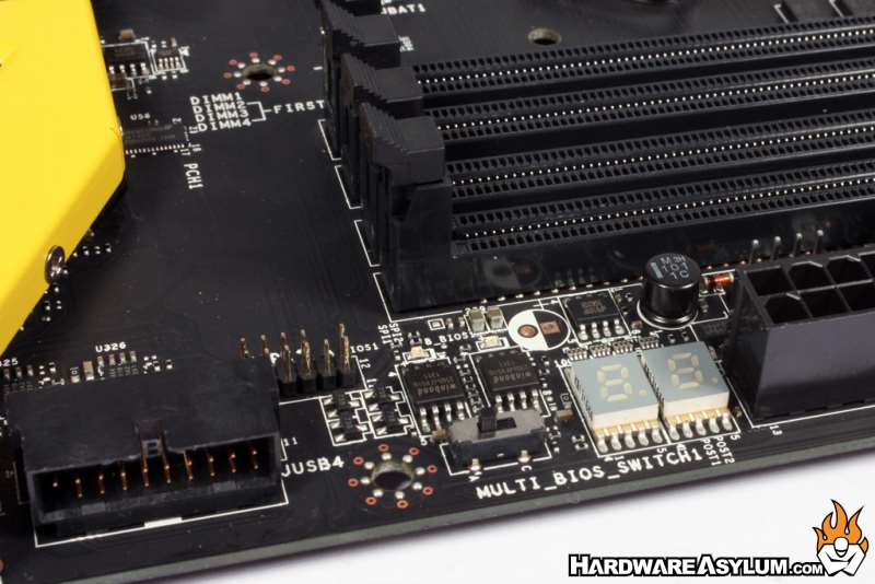
Next to the 24pin power connector you will find three very important features starting with voltage check points to the right. These give you accurate voltage readings so you can check for voltage drops when overclocking and monitor what the system is doing. Below the power connector you'll find a DEBUG LED that indicates the POST condition followed by a Multi BIOS switch that will allow you to boot to either of the two onboard BIOS chips.