MSI MAG B850 Tomahawk Max WiFi Motherboard Review
Author: Dennis GarciaBoard Layout and Features
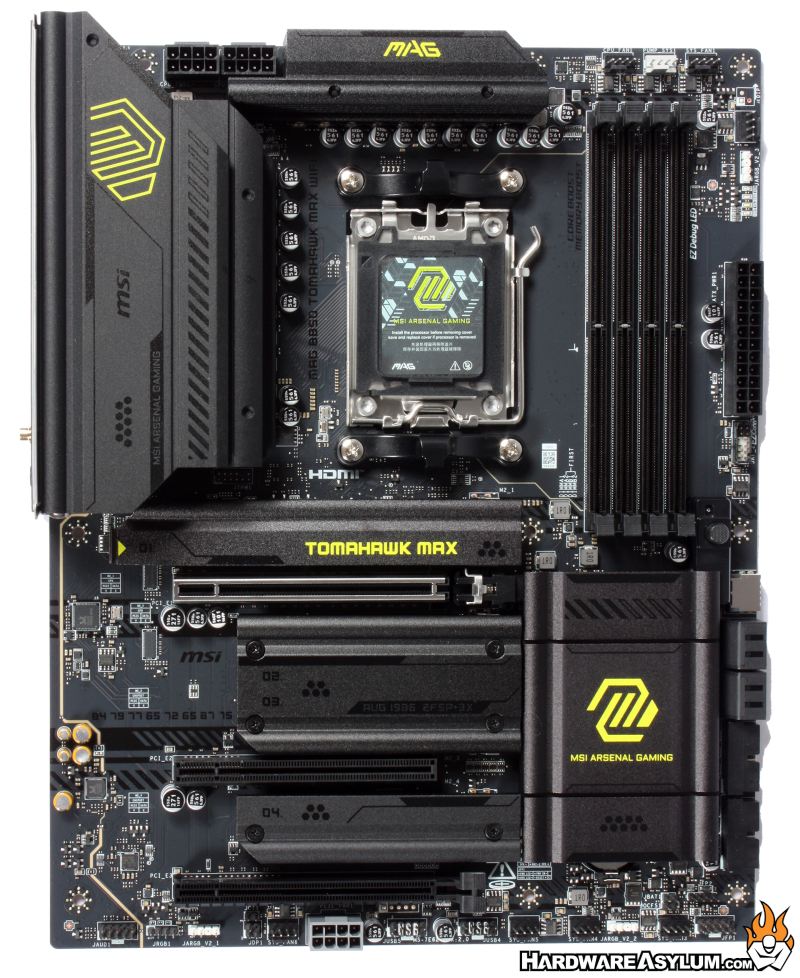
The MSI MAG B850 Tomahawk has a very unique layout that we would have seen back in the days of Multi GPU setups but, falls short on the delivery. At the top you will find a single PCI Express 16x slot with metal reinforcement. This is the only slot getting bandwidth from the CPU and the only PCIe 5.0 slot on the board. While this layout goes a long way in maximizes drive storage it does so without compromising PCI Express slot options for those users wanting a little more.
When presented motherboards in the midrange, you will often see a complete disregard for "design", mostly in an attempt to save money but, there is also a market assumption that consumers buying lower end components are more tolerant of things mot matching or when certain features are missing. For the Tomahawk Max, the design is black on black with some subtle graphics just to provide some aesthetic.
On a personal note, the heatsink and heatspreader designs are kinda meh. The curves that are present on the aluminum parts feel out of place and the overall size and thickness of the M.2 coolers seems a little inadequate by modern standards.
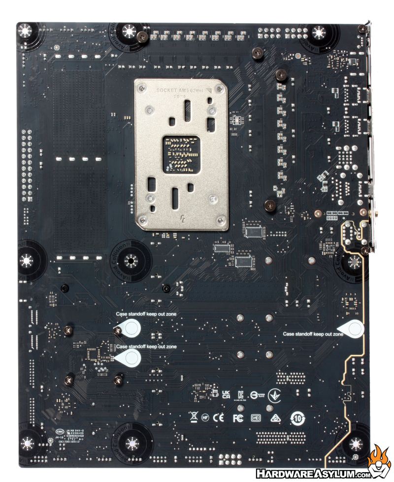
Looking at the back of the motherboard can tell you a lot about how any particular board is constructed. Typically, you’ll see things like how the PCI Express slots are wired up and where the major components are located. With the advent of PCI Express 5.0 many board makers have started to use surface mount expansion slots in an attempt to reduce EMI.
At the bottom of the motherboard, you will find the two expansion slots which are wired with bandwidth from the chipset. The middle most slot is wired to PCIe 3.0 @ 1x while the lower slot is PCIe 4.0 @ 4x. Most everything else is devoid of a through hole solder connection making for a very clean PCB.
I am humored by the warning labels that have been silk screened into the PCB warning people to avoid that location.
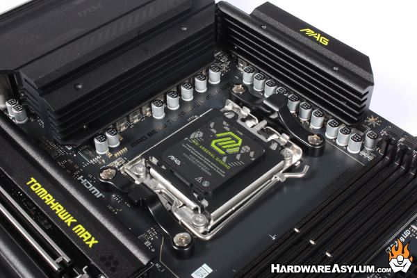
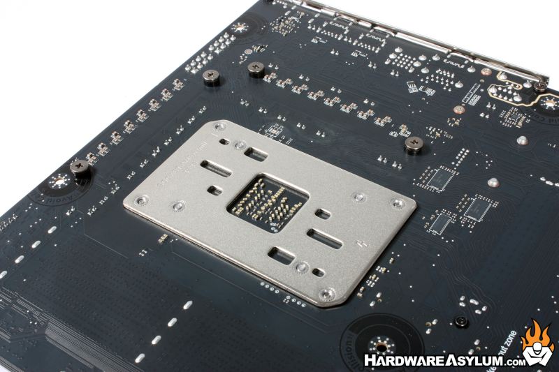
The CPU socket is rather typical for the AM5 platform. Across the top and bottom of the socket you’ll find the heatsink retention brackets and almost always get removed when installing an aftermarket heatsink. What is nice about this configuration is that the backplate remains allowing you to secure everything into a factory part that is extremely strong.
The CPU VRM is a Digital twin 14+2+1 design with a total of 17 VRM power phases with high performance thermal pads and extended heatsink design wrapping around the top sections of the PCB.
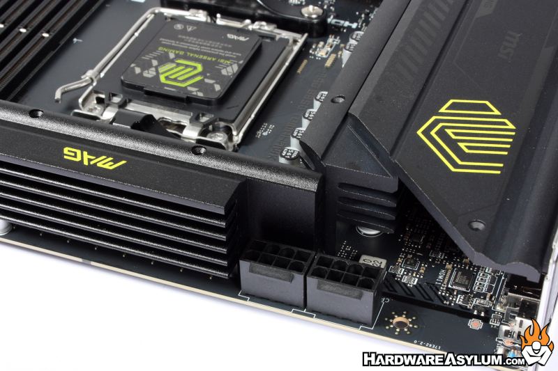
CPU power is delivered by two dedicated 8-pin power sockets located behind the large VRM cooler. While access is tight there is still plenty of room to connect and remove the required cables.