Supra PiModem Project - Getting Retro PCs Online
Author: Dennis GarciaProject Planning
When planning a project like this I find it best to work from a series of prototypes allowing me to test and tune features. It also shows a clear progression of how the project developed during the different stages.
For me, I divided the project up into four sections.
- How to control everything
- How to enable or replicate the front panel display
- How is all of this going to fit inside the Supra FaxModem aluminum shell
- Making it all work together
Bullet point #1 is pretty straight forward. I’ll be using a Raspberry Pi Zero Single Board Computer as the brains of the operation. However, since you cannot buy Raspberry Pi Zero boards I opted for a common alternative, the Banana Pi M2 Zero. From a specification standpoint the Banana Pi should offer a nice performance boost over the Raspberry Pi Zero while still offering the same form factor and interface control.
Think of it as laptops from Dell vs HP, the hardware might be different but, they both run the same software so you can easily adapt.
#2 is a little tricky and required a bunch of detailed soldering.
My original thought was to use the existing board however, after mapping out the circuits I determined that it would be much easier to rebuild the display using some common off the shelf components.
These included:
- Perfboard: which I bought from a seller on ebay.
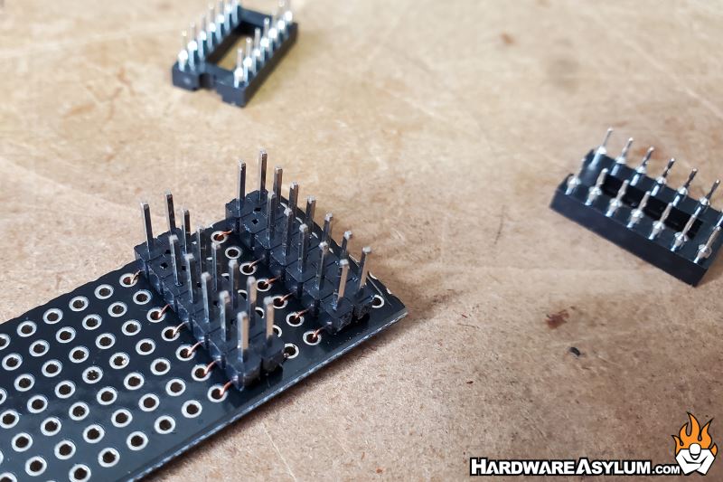
- 14 Pin sockets: These would hold the 5x7 digit displays
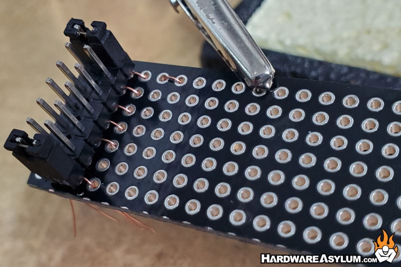
- Straight Pin Headers: I relied on pin headers for all of the major connections allowing me to swap out components without too much trouble.
The first part was to cut down the perfboard to the size I needed for this project. You can do this easily with a utility knife, straight edge, bench vice and pliers. Basically score the board along the perforations and then secure the board in a bench vice and use your pliers to break the PCB along the score line.
I used a standard flat file to clean up the edges and fine tune the fitment.
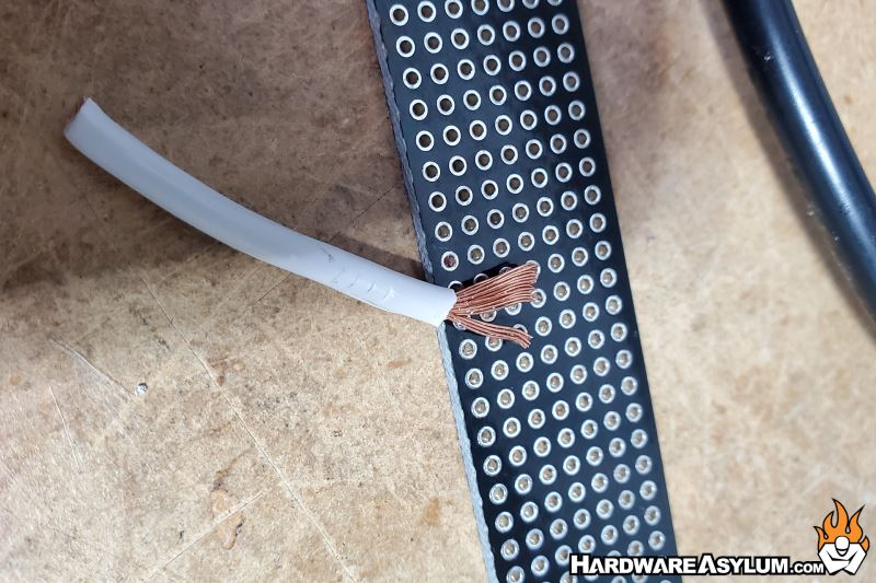
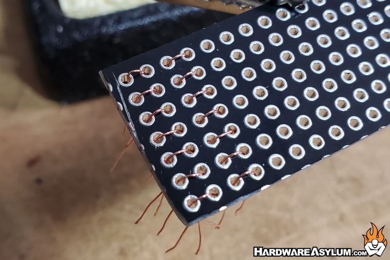
Next, I needed to create a connection between the pin headers and the socket. Since this is perf board is a series of unconnected vias you need to provide a way to connect them together yourself. I am not a fan of the “blobs of solder” approach and decided to go “old skool” and use copper wires to connect the various holes.
For this I used a standard PSU power cable. Each of the three wires/poles is comprised of a striated copper conductor and the gauge was large enough for provide good conductivity while also being small enough to allow for other components to fit in the same via.
It took about three hours to build this circuit and turned out great. If you look carefully, you’ll see the individual copper wires which is duplicated on both sides of the perf board.
A pro-tip is to use a standard jumper to hold the pin headers vertical and keep them aligned and square.
After this the 5x7 dip socket can be installed and soldered in place.