Supra PiModem Project - Getting Retro PCs Online
Author: Dennis GarciaInternal Components and TTL to RS232 module
The TTL board is the heart of this project and will be the primary interface that converts RS232 signals into something that the Raspberry Pi can understand.
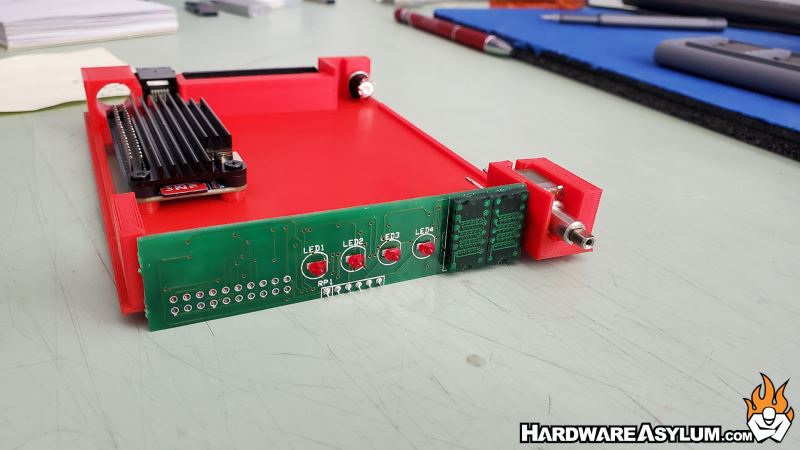
Software controls most of the interaction and all I needed to do is move the activity LEDs to the front panel display.
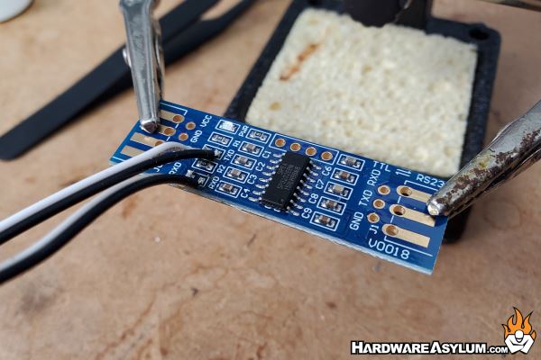
For this I removed the surface mounted LEDs and then extended them with some rainbow wire with DuPont connectors attached.
These will plug directly into the front panel and provide the activity LED interaction needed for the modem.
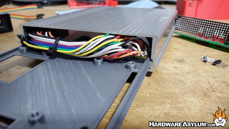
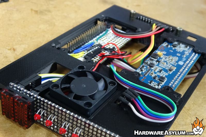
I knew it would be difficult to get everything to fit inside the Supra Modem shell so I started making frames to hold each of the components. The final design looked like this and was designed to fit where the existing PCB was inside the modem.
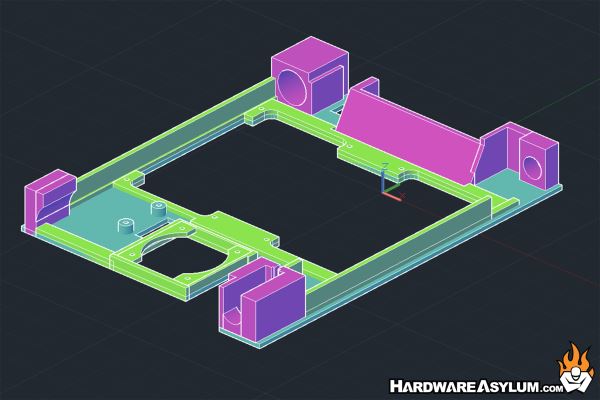
The open area in the middle will hold the Pi Zero boards and the Pi Zero Hat. To simplify the printing process, I modeled induvial “tabs” that would allow me to position the Pi Zero below the board giving more room for the required heatsink and 40 Pin GPIO ribbon cable.
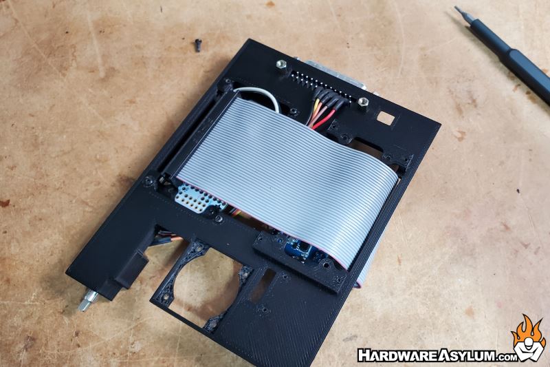
While the Pi Zero will sit below the frame the Pi Hat will actually sit higher and used a different set of tabs.
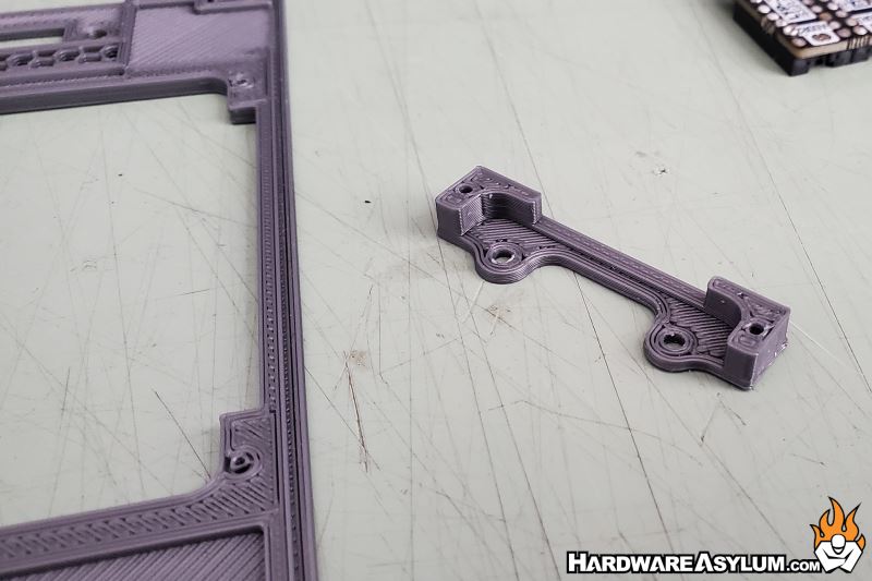
To give you a better idea as to how everything would be laid out here is one of the prototypes. I used this board (and others) to ensure that everything would fit and the holes were aligned correctly.
The prototype frames also allowed me the ability to create custom sets of jumper wires that connected the various components to the Pi Hat Breadboard. Building the breadboard circuits was rather labor intensive and I wasn’t able to get many photos of the process. However, the gist is to route the GPIO connections to the appropriate 90-degree pin headers so they could be connected to the devices inside the modem.
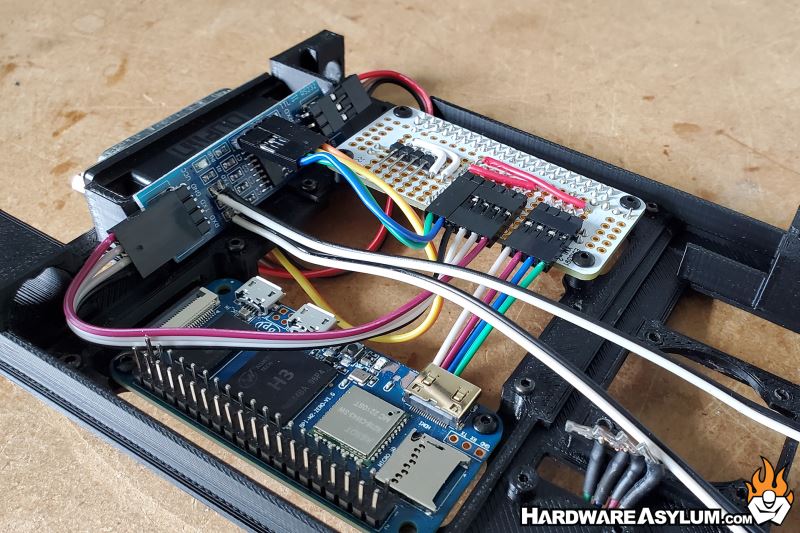
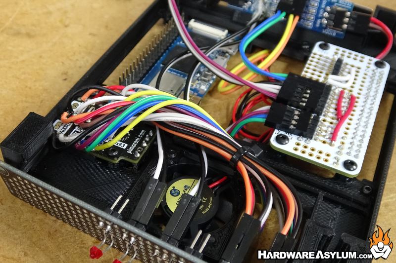
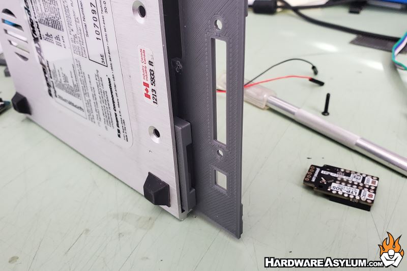
For instance, the Green, Blue, Violet, Grey wire bundle needs to be routed to the i2c module and the six wires next to them is for the TTL board and the final four are the TR and OH LEDs on the front panel.