ASUS ROG Strix B660-i Mini ITX Motherboard Review
Author: Dennis GarciaBoard Layout and Features
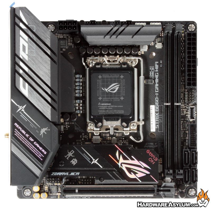
For those who have never seen a Mini ITX motherboard, they are tiny and occupy the upper first four mounting holes found on a standard ATX motherboards. Within that small square you will find everything to make a motherboard work.
The CPU is located in the middle with memory to the right, VRM across the top, expansion slot at the bottom and I/O taking up a large portion of the board to the left.
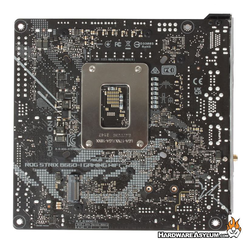
Flipping the motherboard over gives you an indication on how the PCB is constructed. You will find a large number of surface mount components scattered around the PCB along with some pretty cool silkscreen graphics. If you look carefully you’ll find some little space invaders hiding around. Below the CPU socket you’ll find a single M.2 slot for onboard storage and NVMe SSDs which happen to be the first of two available on this motherboard.
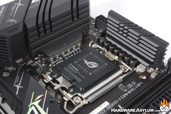
As mentioned the CPU socket is located in the center of the PCB, which is actually the normal location for any ATX motherboard. Counting the power phases has gotten somewhat difficult in recent years but if you look carefully you’ll find six chokes exposed under a VRM cooler and at least three more elsewhere if, we are to believe the ASUS documentation of 8+1.
Under normal loading conditions a total of 9 power phases is plenty to maintain system operations and fits nicely with the down market design of the B series chipsets. We have seen much larger VRM designs on overclocking friendly motherboards that, not only deliver more power but, add significant costs to final design.
To help early adopters of Alder Lake and the Z690 chipset you will find a dual heatsink mounting holes in the PCB supporting the new LGA1700 and older LGA1200/LGA11XX heatsinks. Keep in mind that while you “can” install and older heatsink you will want to ensure that the cooler can handle at least 250w, else you are going to have a bad time.
Behind the VRM cooler you’ll find a single 8-pin CPU power connector along with the available fan headers for CPU and System fans along with a AIO pump header that will allow 100% operation independent of the PWM signals normally reserved for CPU coolers.
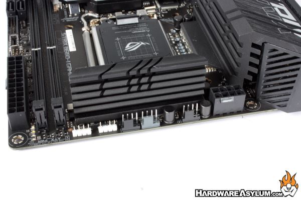
To the left of the fan headers you’ll find two RGB headers. The three pin headers are for ARGB while the four pin header is for the standard analog RGB. Be sure to use the correct header for your build as that will determine what lighting patterns you’ll have available.
You’ll find that Mini ITX motherboards can be rather busy with a multitude of headers and pins scattered around.