TRX40 Aorus Master Gaming Motherboard Review
Author: Dennis GarciaBoard Layout and Features
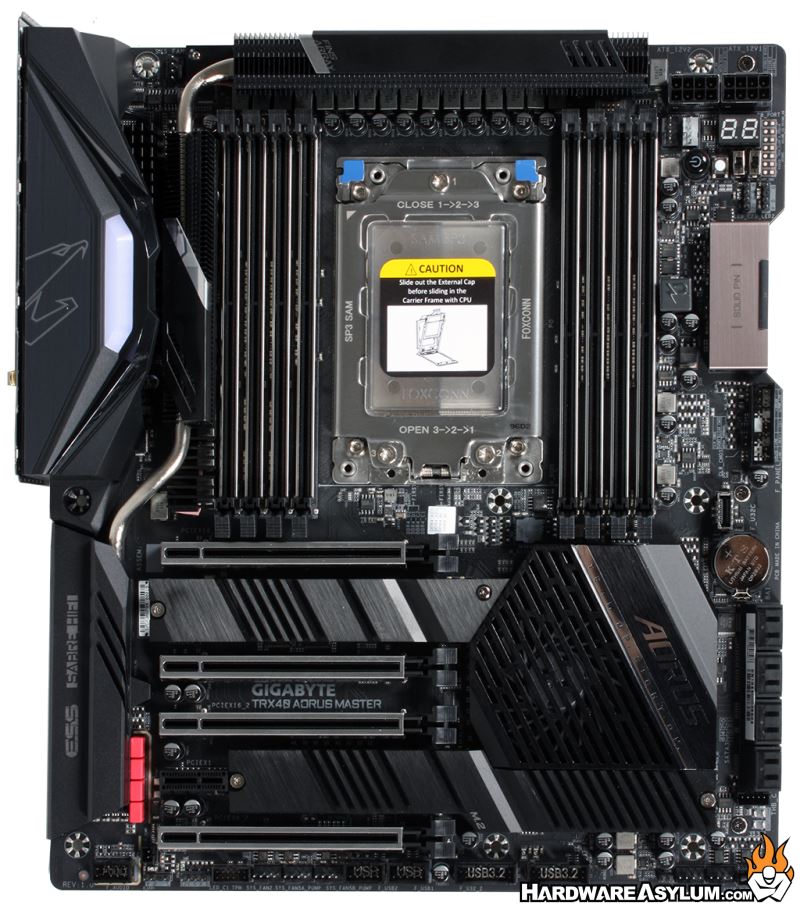
One of the first things you will notice about the Aorus TRX40 Master is the size of the motherboard. It does follow the Extended ATX form factor and will require a larger case properly install it. Most of the additional real estate is to accommodate the large Threadripper CPU and eight memory sockets with the rest dedicated to the multitude of PCI Express lanes the CPU and PCM support.
Other than the size, the board is pretty typical including the heatpipe array of heatsinks, cooler over the chipset and a familiar placement of components right down to the VRM array at the top.
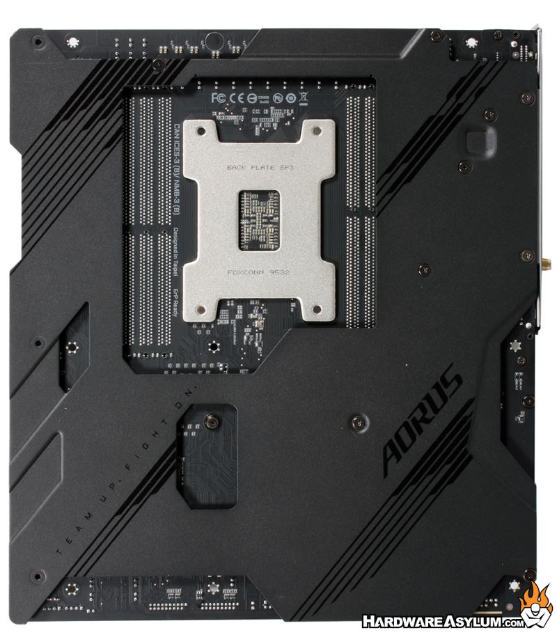
Looking at the back of the motherboard you can normally get an indication as to how the motherboard is constructed, most notability, how the PCI Express slots are wired. In a strange twist for elegance the Aorus Master comes with a full coverage back plate that not only protects the components from damage but will act as a secondary heatsink for everything hot on the Threadripper camp.
So, to get our normal view of the PCB the backplate needed to be removed which will expose all of the components and where the additional thermalpads were placed. Basically there was as thick pad under the 19phase (16+3) VRM and one covering a controller chip near the I/O.
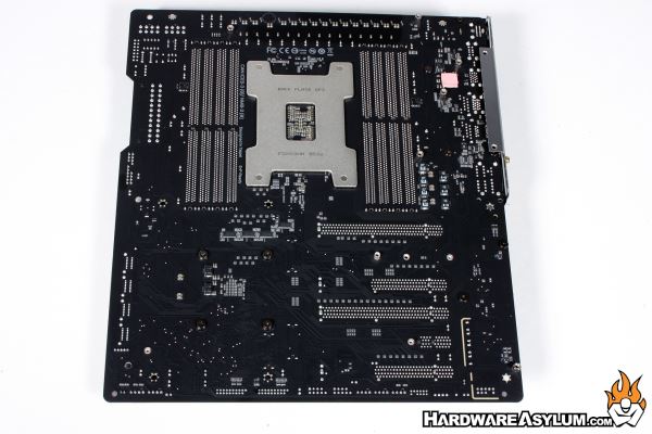
There are a few surface components found on the PCB, very few traces and several normal ATX mounting holes that are filled in. This is an important thing to know as you’ll want to remove those standoffs before installing the motherboard.
Looking around the CPU socket you will find the monster 16+3 phase power supply. There are 16 phases directly above the CPU socket with three more scattered around, likely to support memory function. Overall the CPU area is very clean with a well designed thin-fin cooler to ensure that the VRM is kept chill. Given the construction of the Threadripper CPU you can expect that most users will want to maximize its potential and with a 280w TDP it will be drawing a huge amount of power though the VRM.
The VRM is a Infineon Digital design with a 70A power stage and isn’t using doublers anymore in an attempt to ensure the signal is kept clean while still offering a high phase count.
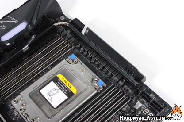
Cooling the VRM heatsink is handled by a heatpipe connected to a larger heatsink connected to the I/O. The primary cooling will happen above the VRM however, for heatpipes to be effective they need somewhere to store excess heat and this is the location.
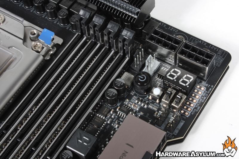
Power connections for the main and CPU are located in the traditional locations. You’ll find the 24pin ATX power connection is mounted at 90degrees near the upper right of the PCB while the two 8-pin CPU power connections are located in the corner closest to the VRM.
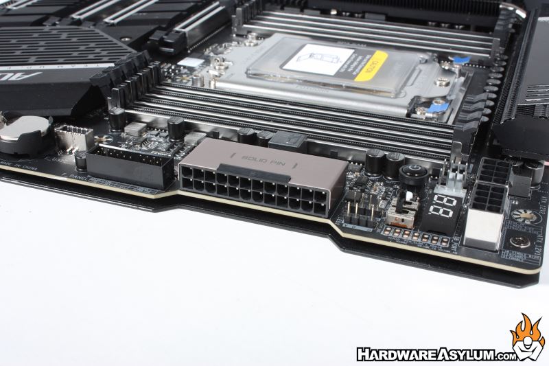
The 90 degree power connection could create a issue when it comes to cable routing. While the parallel solid pin connector does keep the large power connector out of direct airflow it becomes a problem in cases that are not expressly designed for E-ATX motherboard and don’t allow enough room between the edge of the motherboard and the connector. (ask me how I know)